This project, entitled "Development of a hexapod robot", consists of the complete development of the design and construction of an arthropod mobile robot. To develop the prototype, it has been inspired by a formícido called "Messor SP".
In order to carry out this design, a previous study of biomimetism has been carried out. Subsequently through the analysis of kinematic equations (with trigonometry and matrices of Denavit-Hatenberg). Once the simulation of the movements has been obtained, the mechanical modeling has been developed and then its manufacture.
Este proyecto se lo he dedicado a las personas que siempre han confiado en mi, en especial a mi madre y mi padre, el cual pudo ver como evolucionaba hasta sus últimos días.
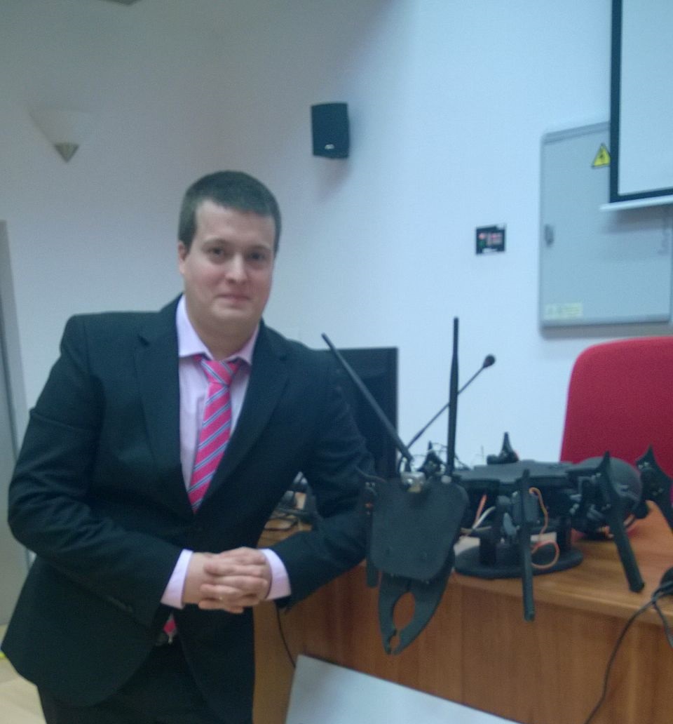
Figure 1: Author with the robot.
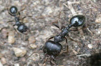
Figure 2: "Messor Sp".
The kinematics study contemplate the equations of movement of the robot, allowing the control of the same and the way of walking on uneven terrain.
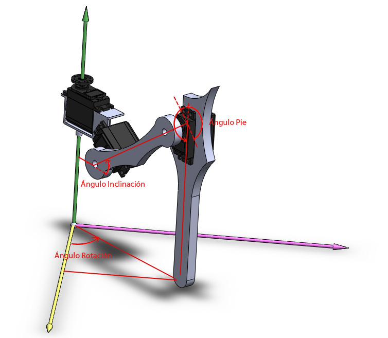
Figure 2: References of angles.
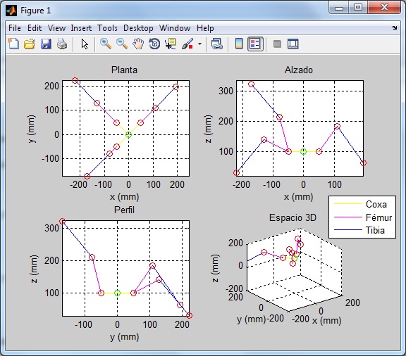
Figure 3: Simulation of kinematics using MatLab.
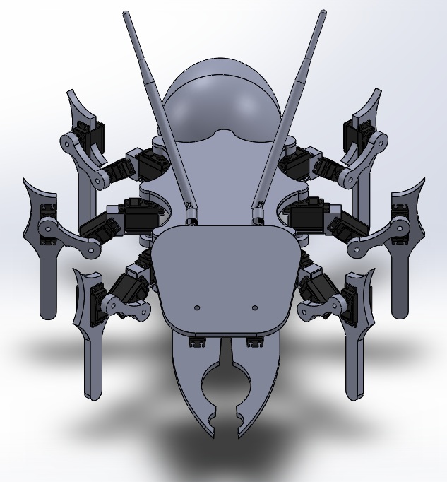
Figure 4: 3D model of the robot.
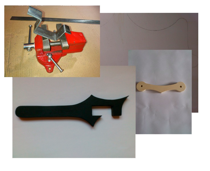
Figure 5: Images of the construction process.
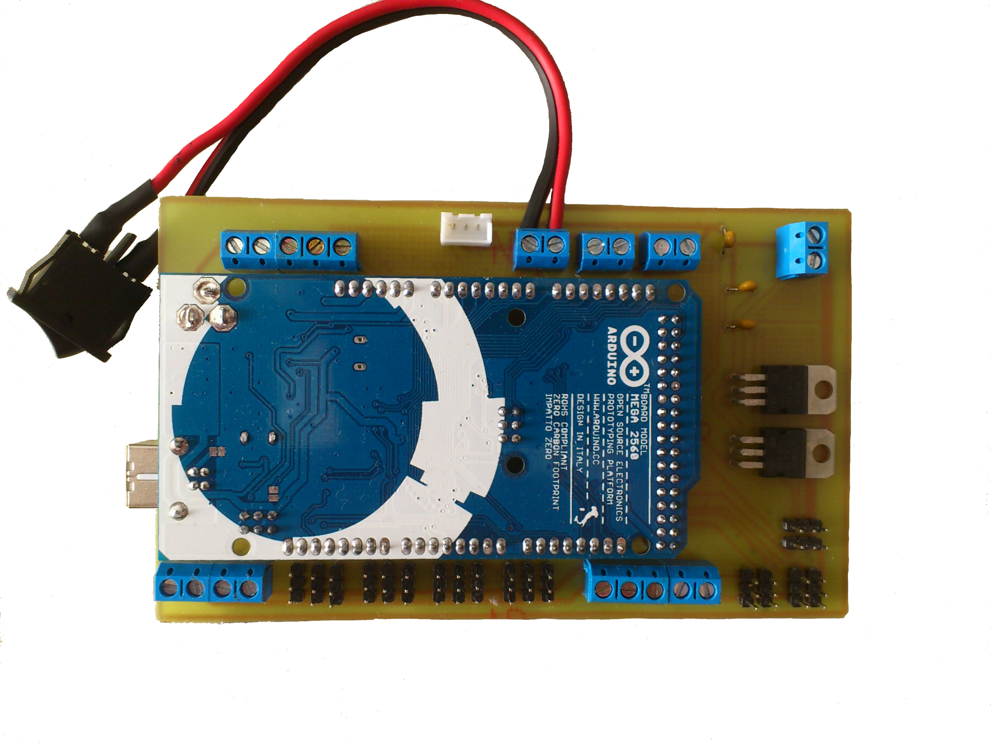
Figure 6: Main Board.
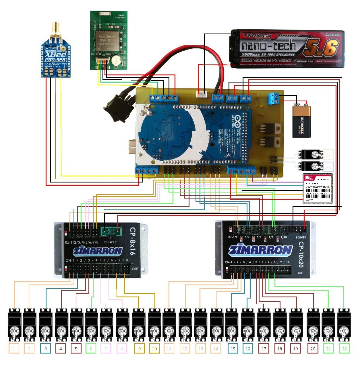
Figure 7: Electrical schematic of the robot.
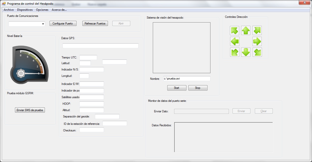
Figure 8: Control program interface.
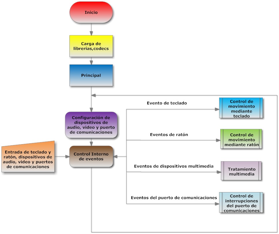
Figure 9: Flow diagram of the operation of the control program.